01 / Digital input
Button-controlled LED
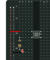
A push button completes a path from the 5 V rail through a 330 Ω resistor and an LED to ground.
Parts: push button · resistor · LED · USB supply
View circuit sourceOpen diagramCircuit cookbook
Each recipe links to a complete Ruby circuit file and a diagram generated from it. Inspect the nets, then adapt the parts and hole positions to your own board.
The cookbook lists all ten examples, including the YAML and TOML versions of the LED circuit.
01 / Digital input
A push button completes a path from the 5 V rail through a 330 Ω resistor and an LED to ground.
Parts: push button · resistor · LED · USB supply
View circuit sourceOpen diagram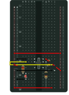
02 / Timing
A timer IC, two timing resistors, and a capacitor form an astable oscillator. A separate resistor limits LED current; the other capacitors bypass supply and control pins.
Parts: NE555 · three resistors · three capacitors · LED
View circuit sourceOpen diagram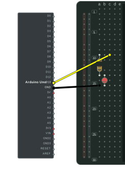
03 / Offboard module
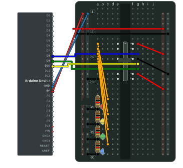
D13 drives an LED through a current limiting resistor. The Uno remains outside the breadboard, where its physical board belongs.
Parts: Arduino Uno · resistor · LED
View circuit sourceOpen diagram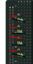
04 / Repeated circuit
A Ruby loop places four independent resistor and LED paths. The resolved nets keep each branch separate.
Parts: four resistors · four LEDs · USB supply
View circuit sourceOpen diagram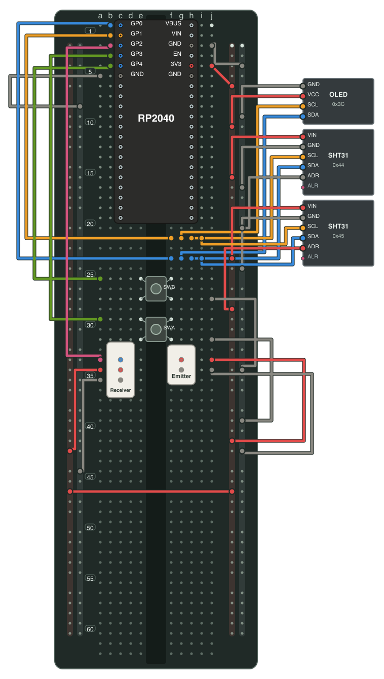
05 / Sensor system
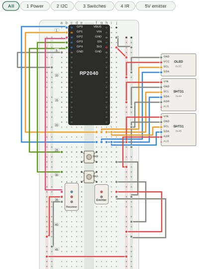
A full-size board combines an RP2040 module, I²C display and sensors, input switches, and an infrared beam. Wire layers separate power, I²C, switches, and IR while sharing the same resolved circuit.
Parts: RP2040 · OLED · two SHT31 modules · two switches · IR receiver and emitter
08 / Serial output
Three Uno pins carry data, clock, and latch signals to a 74HC595. Four outputs drive separate LEDs through 1 kΩ resistors; drive the pins in firmware to animate them.
Parts: Arduino Uno · 74HC595 · four resistors · four LEDs · capacitor
View circuit sourceOpen diagram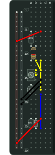
09 / Analog input
Light lowers the photoresistor resistance and biases a 2N3904 transistor, which switches a small 5 V active buzzer. A potentiometer sets the light threshold; a diode protects the transistor.
Parts: photoresistor · resistor · potentiometer · 2N3904 · active buzzer · diode
View circuit sourceOpen diagram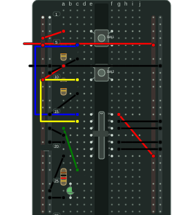
10 / Logic gate
Each button pulls one 74HC08 input high while its resistor holds it low when released. The green LED lights only when both buttons are pressed; unused CMOS inputs are tied low.
Parts: two buttons · 74HC08 · four resistors · LED · capacitor
View circuit sourceOpen diagramStart with the user guide to learn the syntax, or edit a small powered circuit in the Playground.