
Breadkit / Guide
From circuit code to diagram.
Follow a working example from component placement to SVG output. Each diagram below was generated from the code shown beside it.
Set up
Install Ruby and the gems you need. Breadkit describes the circuit, breadkit-render draws it, and breadkit-lint checks it.
gem install breadkit breadkit-render breadkit-lintThis guide documents 0.2.0 on main. If RubyGems is still at 0.1.0, use the source checkouts for YAML, TOML, and newer CLI features. Check breadkit --version after installing.
.bk.rb files run as Ruby. Only load files you trust. Use declarative YAML or TOML when the input must remain data.
Describe a circuit without Ruby
A .bk.yml or .bk.toml file describes the same board, parts, wires, and expected connections as the Ruby DSL. The loader parses these files as data.
title: LED circuit
board: mini
supplies:
  - {name: USB, voltage: 5, plus: a1, minus: a2}
labels:
  - {name: VCC, at: a1}
  - {name: GND, at: a2}
parts:
  - {ref: R1, type: resistor, value: "330", pins: [b1, b3]}
  - {ref: D1, type: led, pins: {anode: c3, cathode: c4}, attrs: {color: red}}
wires:
  - {from: d4, to: b2, color: black}
expectations:
- connected: [[VCC, R1.1], [R1.2, D1.anode], [D1.cathode, GND]]VCC: R1.1, USB.+
GND: D1.cathode, W1, USB.-
N1: R1.2, D1.anodeThe output lists three conductive nets. The wire joins the LED cathode to the ground supply; the resistor separates VCC from the LED anode.
breadkit fmt 06_declarative_led.bk.yml > formatted.bk.yml
bklint 06_declarative_led.bk.yml
bkrender 06_declarative_led.bk.yml -o led.svg --theme dark
Formatting prints normalized data and does not modify the source. It discards comments. See every YAML and TOML field.
Code and output: button and LED
01_led_button.bk.rb places a switch, resistor, and LED on a half-size board. The code is on the left; the generated diagram is on the right.
title "Button-controlled LED"
board :half

supply :USB, voltage: 5.0, plus: "B+1", minus: "B-1"
net :VCC, at: "B+1"
net :GND, at: "B-1"

button :SW1, at: "e10"
resistor :R1, "330", pins: %w[a12 a16]
led :D1, color: :red, anode: "b16", cathode: "b17"

wire "a10", "B+", color: :red
wire "a17", "B-", color: :black

expect do
  connected "SW1.1", :VCC
  connected "SW1.3", "R1.1"
  connected "R1.2", "D1.anode"
  connected "D1.cathode", :GND
  isolated :VCC, :GND
end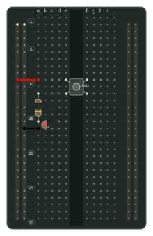
at: "e10" places the switch's first pin in hole e10. pins:, anode:, and cathode: name the holes occupied by component leads. wire joins strips or rails with a jumper.
bkrender 01_led_button.bk.rb -o led.svg --theme dark
bklint 01_led_button.bk.rb
breadkit nets 01_led_button.bk.rb
expect records the intended connections. bklint compares them with the resolved circuit. View the original file.
For executable connection tests, breadkit-rspec provides assertions such as expect(circuit).to connect("R1.2", "D1.anode").
Holes and power rails
Terminal holes use a letter from a to j and a number, such as a10. Rails use T+ / T- at the top and B+ / B- at the bottom. B+1 selects a position; B+ chooses a free hole.
| Reference | Meaning |
|---|---|
| e10 | Hole 10 in column e |
| B+1 | First hole on the bottom positive rail |
| D1.anode | The conductive strip containing D1's anode |
Offboard modules
Use offboard to place an Arduino Uno or another module beside the breadboard and connect wires to its named pins. This diagram was generated from the code shown here.
title "Arduino UNO LED"
board :half
offboard :UNO, "arduino_uno", side: :left

resistor :R1, "330", pins: %w[a10 a14]
led :D1, color: :red, anode: "b14", cathode: "b16"

wire "UNO.D13", "c10", color: :yellow
wire "a16", "UNO.GND", color: :black

expect do
  connected "UNO.D13", "R1.1"
  connected "R1.2", "D1.anode"
  connected "D1.cathode", "UNO.GND"
end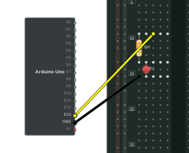
Custom modules define pin names and type: values in YAML. Types such as power, ground, clock, and data also control the pin markers in the diagram. See a module definition.