Breadkit / Components
Components and modules
Place a component by naming the holes for its leads or its anchor hole. Use offboard for modules beside the breadboard, then wire their named pins.
Common components
These built-in definitions support rendering and connection analysis. Hole positions are examples; choose positions that fit your circuit.
| Component | DSL | Placement |
|---|---|---|
| Resistor | resistor :R1, "330", pins: %w[a12 a16] | Two leads |
| LED | led :D1, color: :red, anode: "b16", cathode: "b17" | Two polarized leads |
| Push button | button :SW1, at: "e10" | Across the center gap |
| C&K BD04 DIP switch | part :SW1, :ck_bd04, at: "e20" | Four independent contacts across the center gap |
| Capacitor | capacitor :C1, "10n", pins: %w[h23 h24] | Two nonpolarized leads |
| Electrolytic capacitor | electrolytic :C2, "100u", plus: "g22", minus: "j24" | Positive and negative leads |
| NE555 | ic :U1, "NE555", at: "e20" | Anchor at pin 1 |
The catalog also includes 74HC logic, Arduino Nano and Pico boards, ESP32 DevKitC, Pro Micro, XIAO, analog ICs, drivers, regulators, diodes, transistors, and sensors. BC547 and BC557 use CBE pin order; 2N3904 and 2N3906 use EBC. Run breadkit parts for the exact definitions. Values may use units such as 4.7k or 10uF.
The BD04 contact states are SW1.1 through SW1.4. Select several with breadkit nets --state SW1.1,SW1.4 circuit.bk.rb. Its PnA/PnB pin labels identify actuator positions, not manufacturer terminal numbers. Verify position 1 and orientation against the C&K datasheet before assembly.
The named ShillehTek four-contact MB102 power module requires you to specify all four rail holes and both output selector positions. Its definition does not assume a mounting row spacing shared by other MB102 variants. Follow the power module guide and verify the contact fit on your hardware.
For a source-verified Raspberry Pi Pico W footprint, use the separate breadkit-parts repository. Add it as a Git submodule and run breadkit lock to pin the exact YAML definition used by your circuit.
Define module pins
Define offboard modules such as OLEDs and sensors in YAML. This excerpt from the SHT31 definition names each pin and its type:, which controls the pin marker color.
id: sht31
category: module
placement: offboard
pins:
  - {num: 1, name: VIN, type: power}
  - {num: 2, name: GND, type: ground}
  - {num: 3, name: SCL, type: clock}
  - {num: 4, name: SDA, type: data}
  - {num: 5, name: ADR, type: address}
  - {num: 6, name: ALR, type: interrupt}
render: {shape: offboard, label: SHT31}board :full
use_parts "parts/*.yml"
offboard :SHT31, :sht31, side: :right,
at: "a12", address: "0x44"
wire "SHT31.SCL", "h22", color: :yellow
wire "SHT31.SDA", "h24", color: :blueThe module appears beside the board. Wire SCL and SDA by name, and connect the real power pins too.
For a board-mounted module, define placement: footprint and its pin positions with footprint hole offsets or footprint_mm offsets on the 2.54 mm hole grid. Then place it with at:. See the built-in part definitions and custom examples.
A circuit with several modules
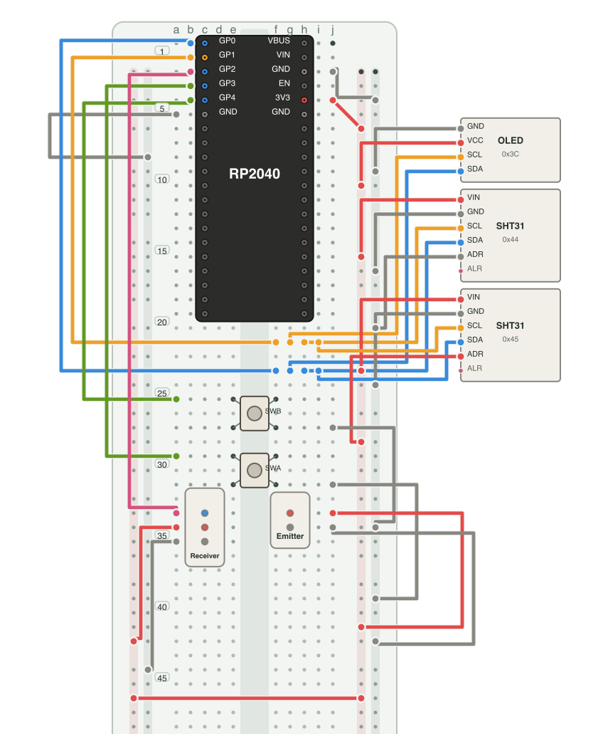
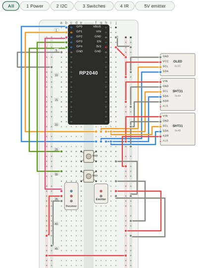
The sensor demo places an RP2040-compatible board on the breadboard and an OLED plus two SHT31 modules beside it. Power, I2C, switches, and IR wiring can be shown layer by layer.